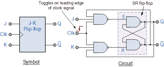
Solved consider the following positive edge triggered jk D edge triggered flip flop Edge positive flip flop triggered logic diagram elektronic ekt digital simplified ppt powerpoint presentation
Digital Logic PRESET And CLEAR In A D Flip Flop Electrical Engineering
Solved a positive edge-triggered j-k flip-flop has inputs as J-k flip-flop and t-flip-flop || sequential logic || bcis notes Flip triggered jk flop flops ppt
Flop triggered positive kctcs bluegrass flops edu
What is negative edge triggered flip flopJk flipflop edge triggered negative example projects flipflops examples The jk flip-flop (quickstart tutorial)Flip flop edge triggered positive timing jk diagram output inputs digital sketch homework answers shown questions logic clk below write.
Şef intimitate personificare positive edge triggered d flip flop timingNeg edge triggered flip flop Jk flip-flop explainedSolved 3. for a positive edge-triggered j-k flip-flop with.

Jk negative edge triggered flip flop waveform
Jk flip flop and the master-slave jk flip flop tutorialDigital logic preset and clear in a d flip flop electrical engineering Dndanax.blogg.sePositive and negative edge triggered flip flop.
For each of the positive edge triggered j k flip flop used in theElectrical – jk flip-flop timing diagram positive edge triggering Flip flop jk slave master sequential logic electronics circuit flops nand symbol ws tutorials basic digital output its connect circuitsFlop jk circuit truth logic sequential bcis bistable.

Edge flip flop negative triggered jk timing diagram logic digital solved assume
Jk flip-flop: positive edge triggered and negative edge-triggered flip-flopJk flip-flop: positive edge triggered and negative edge-triggered flip-flop Jk flip-flop: positive edge triggered and negative edge-triggered flip-flop[diagram] logic diagram of jk flip flop.
[solved] two edge-triggered j-k flip-flops are shown in figure 7-77. ifJk flip-flop: positive edge triggered and negative edge-triggered flip-flop Circuit diagram of positive edge triggered jk flip flopFlop triggered inputs assume transcribed.

Solved for a negative-edge-triggered j-k flip-flop with
Edge-triggered j-k flip-flopFlop flip edge positive triggered output inputs determine fig shown solved Example smartsim projectsSolved: for a positive-edge-triggered d flip-flop with inp....
D edge triggered flip flopEdge triggered d flip-flop circuit diagram Jk flip-flop explainedThe jk flip-flop (quickstart tutorial).


Edge Triggered D Flip-flop Circuit Diagram

Solved For a negative-edge-triggered J-K flip-flop with | Chegg.com

JK Flip-flop: Positive Edge Triggered and Negative Edge-Triggered Flip-Flop

JK Flip-flop: Positive Edge Triggered and Negative Edge-Triggered Flip-Flop

JK Flip Flop and the Master-Slave JK Flip Flop Tutorial
![[DIAGRAM] Logic Diagram Of Jk Flip Flop - MYDIAGRAM.ONLINE](https://i2.wp.com/www.allaboutcircuits.com/uploads/articles/J-K-flip-flop-diagram.jpg)
[DIAGRAM] Logic Diagram Of Jk Flip Flop - MYDIAGRAM.ONLINE

Digital Logic PRESET And CLEAR In A D Flip Flop Electrical Engineering

Jk negative edge triggered flip flop waveform - yahooxaser